






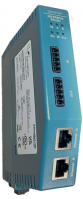
INTERBUS Router
A-IBR
The A-IBR INTERBUS Router provides intelligent data routing between either EtherNet/IP™ or Modbus® TCP and an INTERBUS master.
INTERBUS is a fast sensor–actuator bus for transmitting process data in industrial environments. Due to its transmission procedure and ring topology, INTERBUS features a fast, cyclic, and time‑equidistant process data transmission.
The A-IBR can emulate up to 15 INTERBUS slave devices and map the INTERBUS input and output data to EtherNet/IP or Modbus devices.
Each (virtual) INTERBUS device can be configured for a specific Device Class, Type, Data Direction and Data Width.
The A-IBR is configured using the Aparian Slate application which can be downloaded from www.aparian.com free of charge.
图像

|

|

|

|

|
特性 优势
- The A-IBR can emulate up to 15 INTERBUS slaves
- Supports both INTERBUS Baud Rates (500 kb & 2 Mb)
- Supports various Primary Interfaces:
- EtherNet/IP Target (Class 1 connection)
- Modbus Server (TCP)
- Modbus Client (TCP)
- EtherNet/IP Originator (Class 1 connection with up to 15 EtherNet/IP devices and Explicit Messaging, including Direct-To-Tag Logix tag access, with up to 10 EtherNet/IP devices)
- Slate software provides a Modbus packet capture utility for better diagnosis of issues
- Dual Ethernet ports which support Device-Level-Ring (DLR)
- Small form factor – DIN rail mounted
应用程序
The A-IBR can use one of four Primary Interface modes.
EtherNet/IP Target
As an EtherNet/IP target, a remote EtherNet/IP device (e.g. a Logix controller) establishes several Class 1 connections to the module. INTERBUS data can be mapped into 4 separate input and output class 1 cyclic connections to the Logix controller (allowing up to 2KB input and 2KB output to be exchanged at the requested packet interval – RPI).
EtherNet/IP Originator
As an EtherNet/IP originator, the module can use one of the following methods to read and write data to and from the INTERBUS master:
-
EtherNet/IP Explicit Messaging
This allows an INTERBUS master to exchange data with up to 10 EtherNet/IP devices. The module can use either Class 3 or Unconnected Messaging (UCMM) to Get and Set data in the remote EtherNet/IP devices. -
Direct-To-Tag technology
This allows the INTERBUS master to exchange data with a Logix controller without the need to write any application code (e.g. ladder) in Studio 5000. The INTERBUS slave data is directly read from, or written to, Logix tags. -
EtherNet/IP Class 1 connection
INTERBUS data can be mapped to a maximum of 15 EtherNet/IP devices using input and output class 1 cyclic connections. This will allow the INTERBUS Router to “own” the EtherNet/IP target device and exchange INTERBUS slave data using the EtherNet/IP device’s input and output assemblies.
Modbus Server
The diagnostics and INTERBUS data will be written to, or read from, the module’s internal Modbus Registers (Holding or Input Registers). These registers can be accessed by a remote Modbus Client using Modbus TCP.
Modbus Client
The diagnostics and INTERBUS data will be written to, or read from, the module’s internal Modbus Registers (Holding or Input Registers). The Modbus Auxiliary Map can then be used to configure the Modbus data exchange between multiple remote Modbus Server devices and the module’s internal Modbus registers via Modbus TCP.
配置
The Slate Configuration Utility software is used for configuration and troubleshooting of the module. The stand-alone configuration utility allows users to define the setup and configuration of the INTERBUS Router module, connections with controllers and devices.
规格
Ethernet
| Specification |
Description |
| Connector |
RJ45 |
| Conductors |
CAT5 STP/UTP |
| ARP Connections |
Max 20 |
| TCP Connections |
Max 20 |
| CIP Connections |
Max 15 |
| Communication Rate |
10/100Mbps |
| Duplex Mode |
Full/Half |
| Auto-MDIX Support |
Yes |
| Embedded Switch |
Yes, 2 x Ethernet ports |
| Device Level Ring (DLR) |
Supported |
| Network Time Protocol (NTP) |
Supported |
INTERBUS Ports
| Specification |
Description |
| Connector |
5-way terminal |
| Conductor |
24 to 18 AWG |
| Electrical Isolation |
1000 Vrms for 1 minute |
INTERBUS
| Specification |
Description |
| Type |
Slave |
| Max. Device Count |
15 |
| Max. Total INTERBUS Data |
128 bytes |
| Max. Summation Frame |
128 bytes |
| Parameter Channel (PCP) |
Not Supported |
| Supported BAUD Rates |
500kbps, 2Mpbs |
EtherNet/IP™ Target
| Specification |
Description |
| Class 1 Cyclic Connection Count |
4 |
|
Logix Direct-to-Tag |
Yes |
EtherNet/IP™ Originator
| Specification |
Description |
|
| Class 1 Cyclic Connections Supported |
Yes |
|
| Class 3 / UCMM Connections Supported |
Yes |
|
| Class 1 Connection Count |
15 |
|
| Class 3 / UCMM Target Device Count |
10 |
|
| Class 3 / UCMM Mapping Count |
50 |
|
Modbus® Client
| Specification |
Description |
| Modes Supported |
Modbus TCP |
| Max. Modbus Server Devices |
20 |
| Max. Modbus Mapping |
100 |
| Mapping Ranges |
Holding Register 0 to 4999 Input Register 0 to 4999 Input Status 0 to 4999 Coil Status 0 to 4999 |
| Base Offset |
Modbus (Base 0) |
| Configurable Modbus TCP Port |
Yes |
| Data Reformatting Supported |
BB AA |
Modbus® Server
| Specification |
Description |
| Modes Supported |
Modbus TCP |
| Mapping Ranges |
Holding Register 0 to 4999 |
| Base Offset |
Modbus (Base 0) |
| Configurable Modbus TCP Port |
Yes |
硬件
| Specification |
Description |
|
| Power Supply |
Input: 10 to 32 VDC |
|
| Power Consumption |
3.0 W (Max.) |
|
| Dimensions |
149.0 x 34.0 x 116.0 mm (H x W x D) |
|
| Connector |
3-way terminal |
|
| Conductors |
24 to 18 AWG |
|
| Enclosure Rating |
IP20, NEMA/UL Open Type |
|
| Temperature |
-20° to 70°C, -4° to 158°F |
|
| Earth Connection |
Yes, terminal based |
|
| Emissions |
IEC61000-6-4 |
|
| ESD Immunity |
EN 61000-4-2 |
|
| Radiated RF Immunity |
IEC 61000-4-3 |
|
| EFT/B Immunity |
EFT: IEC 61000-4-4 |
|
| Surge Immunity |
Surge: IEC 61000-4-5 |
|
| Conducted RF Immunity |
IEC 61000-4-6 |
|